
Use a pushbutton to select between addition and subtraction. reg op1, op2 Īlways ( posedge(clk)) begin if (btn) op1 <= sw Ĭonfigure the adder to be an adder/subtractor by including a circuit that can change one of the operand inputs into its negated two’s-compliment form (i.e., invert all the bits and add one). Since the inputs are 8-bit binary numbers, you should use a seven-segment controller than can generate hex digits as well as BCD digits. Connect the adder’s output to two digits of the seven-segment display. Connect the adder’s inputs to two banks of eight slide switches. Adder/SubtractorĬreate an 8-bit adder using the Verilog addition operator ("+"). Use eight slide switches to define the inputs, and display the output on two digits of a seven-segment display.

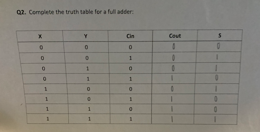
Simulate your circuit to verify its function, and then program it into the Boolean board. 4-bit CLAĭefine a 4-bit CLA using structural Verilog (i.e., define a module for the bit-slice component and a module for the CPGN network, and then connect four bit-slice modules to the CPGN). The fact that we’re looking at signals as bits in binary numbers doesn’t change the design methods used to find an efficient circuit. If you don’t focus on this abstraction, and just think of the inputs and outputs as signals, then the adder design is no different than any other combinational logic circuit design (apart from the larger truth table). With arithmetic circuits like an adder, there is a stronger association between the input 1’s and 0’s, and the abstraction to a logical binary number (instead of just individual signals). As the truth table above shows, a 16-input, 8-output combinational logic circuit can be defined, with the eight output logic functions forming the eight bits of a binary number that is the sum if the two inputs.īut there is a difference in context.

But really, arithmetic circuits are no different than the logic circuits we have been working with – they just have more inputs and more outputs. A truth table for an 8-bit adderĪdding binary numbers seems a different and more abstract problem than combining logic signals using simple logic gates. This is called the “bit slice” design method. Of course, the goal is to design just one circuit that operate on any pair of bits, and then to replicate that exact same circuit n times. In the case of a circuit that operates on busses, one approach is to break up the overall design into a collection of smaller circuits that each operate on a pair of bits, and then to use as many of the bit-pair circuits as are needed to address the overall n-bit circuit.


 0 kommentar(er)
